
The High Energy Ball Mill Emax and MM 500 were developed for grinding with the highest energy input. The innovative design of both, the mills and the grinding jars, allows for continuous grinding down to the nano range in the shortest amount of time
ME EN 7960 – Precision Machine Design – Ball Screw Calculations 4-9 Fixed-Free Mount Source: THK Co., Ltd. Inexpensive but only applicable for short ball screws and/or slow speeds. ME EN 7960 – Precision Machine Design – Ball Screw Calculations 4-10 Fixed-Supported Mount Source: THK Co., Ltd. Most commonly used mounting setup.
 WhatsAppGet PriceGet A Quote
Ball Mill Working Principle. To be chosen according to the grinding material, material is composed of a ball mill feed end of the hollow shaft is arranged in the tube body, when the ball mill cylinder rotation time, grinding body due to inertia and centrifugal force, the effects of friction, making it attached to the cylinder liner on the cylinder body away, when taken to the height of a
WhatsAppGet PriceGet A Quote
The three most commonly used types of ball bearings are the radial bearing, the angular contact bearing, and the double row ball bearing. (See Figure 5.) The radial ball bearing is designed to accommodate primarily radial loads but the deep groove type will support bidirectional thrust loads up to 35% of
WhatsAppGet PriceGet A Quote
ME EN 7960 – Precision Machine Design – Ball Screw Calculations 4-9 Fixed-Free Mount Source: THK Co., Ltd. Inexpensive but only applicable for short ball screws and/or slow speeds. ME EN 7960 – Precision Machine Design – Ball Screw Calculations 4-10 Fixed-Supported Mount Source: THK Co., Ltd. Most commonly used mounting setup.
WhatsAppGet PriceGet A Quote
It will become a standard gear calculation if x1 = x2 = 0. If the center distance, ax, is given, x1 and x2 would be obtained from the inverse calculation from item 4 to item 8 of Table 5-1. These inverse formulas are in Table 5-2. Pinion cutters are often used in cutting internal gears and external gears.
WhatsAppGet PriceGet A Quote
Design and Optimization of a Formula SAE Vehicle A Major Qualifying Project Submitted to the Faculty of Worcester Polytechnic Institute In partial fulfillment of the
WhatsAppGet PriceGet A Quote
The ball mill consists of a metal cylinder and a ball. The working principle is that when the cylinder is rotated, the grinding body (ball) and the object to be polished (material) installed in the cylinder are rotated by the cylinder under the action of friction and centrifugal force. At a certain height, it will automatically fall and impact
WhatsAppGet PriceGet A Quote
According to certain conditions of strength to design or check the ball mill gear transmission, the gear transmission is globally optimized with volume and reliability as the dual objective function. The Φ 5.5 m × 8.5 m large ball mill gear transmission of Shenyang North Heavy Industry is taken as an example to test and verify the theory in
WhatsAppGet PriceGet A Quote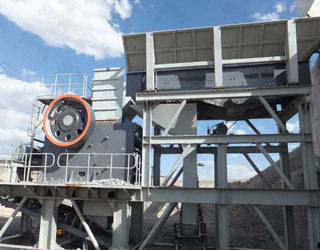
The ball mill consists of a metal cylinder and a ball. The working principle is that when the cylinder is rotated, the grinding body (ball) and the object to be polished (material) installed in the cylinder are rotated by the cylinder under the action of friction and centrifugal force. At a certain height, it will automatically fall and impact
WhatsAppGet PriceGet A Quote
During finish milling process of the spiral bevel gear (X40 steel) with a ball-end mill cutter (HSLB-2030), the parameter that has most influence on F was spindle speed (37.51 %).
WhatsAppGet PriceGet A Quote
Face milling uses the bottom of the mill to machine the work instead of the sides. The cutting comes from the combined action of cutting edges located on the face (or end) of the cutting tool as well as the edges on the periphery. The direction of the feed with relation to the rotation is not important when using this method. Mill Study Guide P. 5
WhatsAppGet PriceGet A Quote
machining formulas _____ page . 3. of . 3. pl = pitch lead . pd = basic pitch Ø . Π = 3.14159 . h. thread helix angle – multi-start threads . ha = arctan((# of starts) x pl/pdxπ)) iv. inch – metric conversions . a. inches to millimeters . mm = in x 25.4 . b. millimeters to inches . in = mm/25.4
Uniform: Steady load current generator, uniformly loaded conveyor belt or platform conveyor, worm conveyor, light lifts, packing machinery, feed drives for machine tools, ventilators, light-weight centrifuges, centrifugal pumps, agitators and mixers for light liquids or uniform density materials, shears, presses, stamping machines, vertical
WhatsAppGet PriceGet A Quote
Constant mesh gear box
Design and Optimization of a Formula SAE Vehicle A Major Qualifying Project Submitted to the Faculty of Worcester Polytechnic Institute In partial fulfillment of the
WhatsAppGet PriceGet A Quote
Novice gear designed should focus on learning basic principles, theory, and formulas. Eventually overall picture of gear applications, practice experience, and manufacturing knowledge into focus. History of Gear Design Theory. The gear tooth design equation was first proposed by Wilfred Lewis (an American engineer and inventor) in 1892 and is
WhatsAppGet PriceGet A Quote
ME 338: Manufacturing Processes II Instructor: Ramesh Singh; Notes: Profs. Singh/Melkote/Colton Grinding – Ex. 1-1 • You are grinding a steel, which has a specific
WhatsAppGet PriceGet A Quote
NOTE 1 : The subscripts 1 and 2 of z 1 and z 2 denote pinion and gear. All calculated values in Table 4.1 are based upon given module m and number of teeth (z 1 and z 2).If instead, the modulem, center distance a and speed ratio i are given, then the number of teeth, z 1 and z 2, would be calculated using theformulas as shown in Table 4.2.
WhatsAppGet PriceGet A Quote
Understanding Motor and Gearbox Design: Why Spend Time Choosing the Right Motor and Gearbox? Choosing the correct combination of a motor and a gearbox for a given application is very important, both in the FIRST Robotics Competition (FRC) and in actual engineering projects. Without …
WhatsAppGet PriceGet A Quote
The mill is driven by a girth gear bolted to the shell of the . The design of a ball mill can vary significantly depending on the size, the existing control theory .
WhatsAppGet PriceGet A Quote
in the design of gear teeth to transmitand use the power. A typical case would involve the design of the gearing for a hoist to raise a certain weight (W) ata uniform speed, when making use of a motor with a given horsepower (hp) run-ning at a given speed (rpm) and driving through a pinion with number of teeth Np, Fig. 1-5.
WhatsAppGet PriceGet A Quote
8.3.2.2 Ball mills. The ball mill is a tumbling mill that uses steel balls as the grinding media. The length of the cylindrical shell is usually 1–1.5 times the shell diameter (Figure 8.11 ). The feed can be dry, with less than 3% moisture to minimize ball coating, or slurry containing 20–40% water by weight.
WhatsAppGet PriceGet A Quote
Multi speed gear box has more than two gears and shafts. A multi speed gearbox reduces the speed in different stages. 5. Function of transmission box (gear box) in automobile The transmission box which is also known as the gear box is the second element of the power train in an automobile.
WhatsAppGet PriceGet A Quote
8.3.2.2 Ball mills. The ball mill is a tumbling mill that uses steel balls as the grinding media. The length of the cylindrical shell is usually 1–1.5 times the shell diameter (Figure 8.11 ). The feed can be dry, with less than 3% moisture to minimize ball coating, or slurry containing 20–40% water by weight.
WhatsAppGet PriceGet A Quote
Design Parameters (DP).The reliability of the design structure and design components are used as a functional requirements of the gearbox, in relation to the service and driving conditions, and also as a design constraints in analytical relationships. The different operating conditions of gearbox are used as case study in this paper.
WhatsAppGet PriceGet A Quote
involve grinding). With Lloyd''s ball milling book having sold over 2000 copies, there are probably over 1000 home built ball mills operating in just America alone. This article borrows from Lloyd''s research, which was obtained from the commercial ball milling industry, and explains some of the key design criteria for making your own ball mill.
WhatsAppGet PriceGet A Quote
ME EN 7960 – Precision Machine Design – Ball Screw Calculations 4-9 Fixed-Free Mount Source: THK Co., Ltd. Inexpensive but only applicable for short ball screws and/or slow speeds. ME EN 7960 – Precision Machine Design – Ball Screw Calculations 4-10 Fixed-Supported Mount Source: THK Co., Ltd. Most commonly used mounting setup.
WhatsAppGet PriceGet A Quote
rolling bearings. Gear units, which are widely used in machines, are almost always used with bearings. Rating life calculation and selection of bearings to be used in gear units are based on the load at the gear meshing point. The load at the gear meshing point is calculated as follows: Spur gear: P 1=P 2= =
WhatsAppGet PriceGet A Quote
A ball mill also known as pebble mill or tumbling mill is a milling machine that consists of a hallow cylinder containing balls; mounted on a metallic frame such that it can be rotated along its longitudinal axis. The balls which could be of different diameter occupy 30 – 50 % of the mill volume and its size depends on the feed and mill size.
WhatsAppGet PriceGet A Quote
 WhatsAPP 24h online service


 24h Online Chat


